

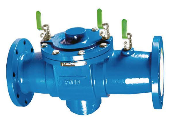
Main External Dimensions:
| Nominal Diameter | Valve Length(mm) | Weight(kg) |
|---|---|---|
| 40 | 330 | 18 |
| 50 | 330 | 18 |
| 65 | 345 | 23 |
| 80 | 365 | 25 |
| 100 | 430 | 28 |
| 150 | 475 | 42 |
| 200 | 565 | 65 |
Installation Location:
1.On the service pipe from the municipal network to the user,located between the water meter and the valve.
2.On the inlet pipe of the fire pump connector or on the fire service outlet pipe.
3.On the water supply pipeline where chemicals are injected into the system.
4.On the cold water inlet pipe of heaters,and on other water supply pipelines where backflow may occur.
Installation Requirements:
1.Clean all pipelines before installation.
2.The backflow preventer shall be installed horizontally in accordance with the arrow direction on the valve body.The installation location shall facilitate commissioning and maintenance.
3.Maintenance gate valves shall be installed at both ends of the backflow preventer.A strainer/filter shall be installed upstream of the inlet, and a flexible connector shall be provided at one end.
4.The drain outlet of the relief valve shall be no less than 300mm above the ground.A drainage trench shall be provided beneath the relief valve.
5.After installation,for initial startup,close the outlet gate valve and slowly open the inlet gate valve to allow the medium to fill the backflow preventer gradually.Open each test ball valve to vent the air from the valve.After the valve chamber is fully filled with water, slowly open the gate valve to allow water to fill the entire pipeline.
6.When the inlet medium pressure fluctuates,a slight leakage from the relief valve is normal.

Copyright © 2026 PT PRATAMA VALVE INDO